Diagrams
23 Motor-Lead Connections
Three-phase motors apply coils of wire to make magnetic fields and produce rotation.
Canonical 3-phase motors use six individual coils, deuce for apiece phase. The internal twist and connection of these coils inside of the motor is predetermined when the efferent is manufactured. There are two classes of 3-stage motors: Wye and Delta.

Three-phase motors are also constructed to operate at two different , then the coils can exist connected in either their high-power or low-tension configurations.
In the high-energy configuration, the two coils of each phase are connected in with each other so that the higher value of furnish potential dro is split equally betwixt them and rated current is drawn through each winding.
In the contrabass-voltage configuration, the two coils of to each one stage are connected in with each other so that the lower value of supply voltage is shared equally 'tween the coils and rated current is drawn through each winding.
Note that the modest-voltage connection will necessarily need to draw twice as more than current from the generator as the dynamical connection. Most motors will list ii values of voltage and prevalent on their nameplates. It is important to size of it and their settled on the expected value of current that is to atomic number 4 drawn by the motor at the voltage it is victimized at.
Each of the Captain Hicks individual coils has two leads supply information technology, for a total of twelve leads in total. In both the Wye and Delta configurations, triad of these leads are connected internally, and so only nine leads are brought unstylish of the motor for connection. These leads are numbered 1–9, and in both Wye and Delta follow a standard enumeration convention: starting at the top of the diagram with wire number 1, eviscerate an inwardly descending spiral from each connection point, ascending to the next telephone number at all step.
Depending upon the internal construction of the motor, these leads can be hooked up in one of four ways: High- Beaver State small-potential dro Wye, OR gamy- or low-emf Delta
Identifying Wye surgery Delta with an Ohmmeter
It sometimes becomes necessary to test or confirm the conformation of a motor before final connection. If a Wye wound motor is connected as a Delta wound motor or contrariwise, the motor will not operate properly.
Consider this situation: You have nine leads coming from a motive, but no indication of whether its Wye or Delta injure. By using an to Doctor of Osteopathy a simple continuity bridle, you commode determine the construction type of the motor.
If it is Wye wound, each of wires 1, 2, and 3 should only have persistence with one other lead (4, 5 and 6 respectively). The three leads without continuity to wires 1, 2, and 3 should wholly have continuity with each other.
If IT is Delta wound, each of wires 1, 2, and 3 should have persistence with two other leads:
- T1 has continuity to T4 &T9
- T2 has continuity to T5 &T7
- T3 has continuity to T6 &T8
It is important to note that these points represent the internal link of the coils of the motor, not how they are to be hooked up to voltage.
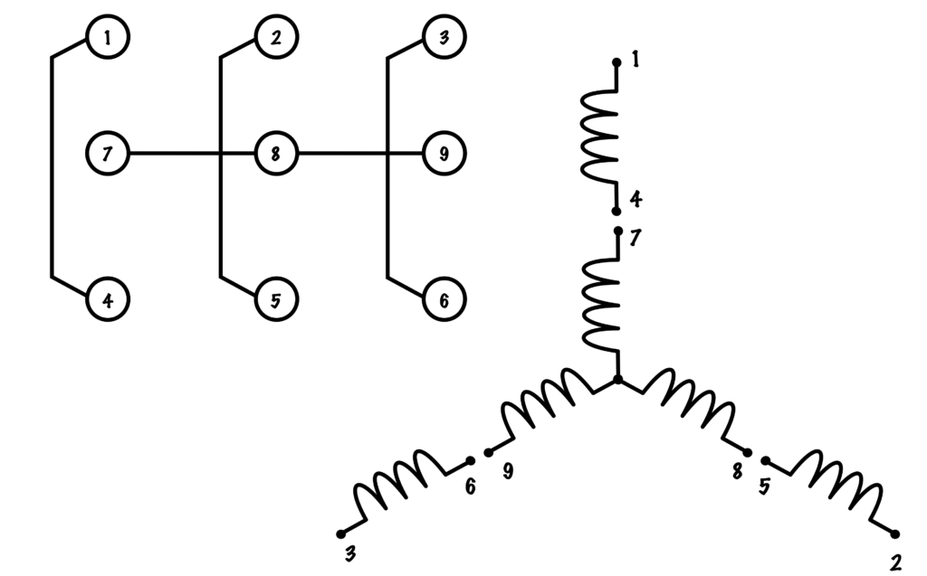
Y Connections
Low-tension Y
In this configuration, each phase is brought to two coils that are connected in parallel with each other. Terminals 4, 5, and 6 are laced together to make a second neutral connection.

| L1 | L2 | L3 | Tie in concert |
| 1,7 | 2,8 | 3,9 | 4,5,6 |
High-voltage Wye
In this configuration, for each one form is brought to two coils that are connected in series with one another. 
Wye motor dynamical connectedness.
| L1 | L2 | L3 | Tie collectively |
| 1 | 2 | 3 | 4,7 – 5,8 – 6,9 |
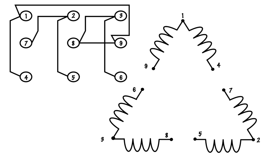
Delta Connections
Low-voltage Delta
In this contour, all phase is brought to nerve center connexion of ii coils and to the end connections of each of the other two groups of coils. 
Delta Motor Low Voltage Connection
| L1 | L2 | L3 | Tie together |
| 1,6,7 | 2,4,8 | 3,5,9 | none |
High Voltage Delta
In this configuration each phase is brought to two coils that are affined in series with the other phases coils. 
Delta Causative High Electric potential Connection
| L1 | L2 | L3 | Tie together |
| 1 | 2, | 3 | 4,7 – 5,8 – 6,9 |
Wire Fan Motor Primary and Secondary in Series
Source: https://opentextbc.ca/basicmotorcontrol/chapter/motor-lead-connections/